Polyserve
Polyserve, which was recently bought by HP, is a clustered NAS vendor that has focused on HPC, web serving, and databases. Their file serving product for Linux, called Polyserve File Serving Utility can have up to 16 file serving nodes with a file system (called the Polyserve Cluster File System - PSFS) behind them. The file system is typically built using SAN hardware. Polyserve's Clustered NAS is a symmetric design where each of the file serving nodes provides all services (metadata, client, and data server). It follows the hybrid design where a single file server acts as a gateway node for the client and gathers the data for the client. In essence they are gateway nodes from the client to the file system.The layout is fairly simply. You have a number of file servers (up to 16), that are plugged into the client network using TCP connections. Then the file servers are plugged into a SAN storage network so they have shared storage. Figure Twelve below shows the basic layout:
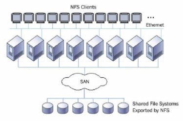
Typically, the file servers are plugged into the network using a single GigE connection and then connected into a Fibre Channel (FC) network for the storage. Polyserve supports Qlogic and Emulex HBA's for the FC network and supports RHEL and SLES on the file servers.
To achieve the symmetric architecture, PSFS uses a symmetric distributed lock manager. A lock manager is important for ensuring that the cache across all of the servers is kept consistent. In PSFS, all of the servers participate in coordinating locks across the storage and the load is balanced as best as possible to reduce bottlenecks. If a node fails, the locks that it was coordinating are moved to other servers. You can also add servers (maximum total is 16), while the file system is in use with no data migration required. The same is true for adding storage
The clients access Polyserve using NFS. In tests, Polyserve says that they get about 120-123 MB/s per server. So for 16 servers you could up to 2 GB/s in aggregate.
Polyserve also has its own volume manager called Cluster Volume manager (CVM). It allows storage volumes to span multiple arrays and stripe data across multiple LUNs or arrays. PSFS supports 128 LUNs per volume, 216 volumes per cluster and 512 file systems per cluster with each file system being limited to 128 TB. So you can scale PSFS to a very large file system. You can also add storage to existing LUNs to grow the storage space within the limits mentioned previously.
Isilon IQ
Isilon is also a clustered NAS solution that can be used for HPC and clusters. The design of Isilon IQ was configured such that you can scale the capacity (amount of storage) and the aggregate performance independent of one another. So if you didn't need as much performance but needed more storage, Isilon IQ allows you to scale capacity. You can also add more gateways to the cluster to provide a larger aggregate throughput (but you are ultimately limited in performance to one gateway server per client).
Since Isilon is a cluster NAS solution, it is organized in a fashion similar to Polyserve. The Isilon file system, called OneFS, is a parallel file system that allows you to add storage servers to expand the file system. But even as you add storage servers, you still have a single name space. But in contrast to Polyserve, you can add as many gateway nodes (file servers) as you want or need. Figure Thirteen is a diagram of an Isilon layout:
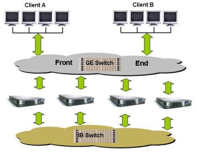
The Isilon servers are called "IQ". The model number of the IQ product is determined by the size of the disks in the server. Each IQ box has 12 hot-swappable disks. Currently the IQ 1920i uses 160 GB SATA drives (1.92 TB usable space), the IQ 3000i uses 250 GB SATA drives (3.00 TB usable space), the IQ 6000i uses 500 GB drives (6.0 TB usable space), and the IQ 9000i uses 750 GB drives (9.00 TB of usable space). Each IQ unit is 2U high and has two outgoing GigE connections (only one is used and the other one is a failover), and 2 InfiniBand connections to the file system network (again, only one is used and the other is a fail over connection). Each server has 4 GB of memory and 512 MB of NVRAM (Non-volatile RAM).
Isilon uses InfiniBand for the storage network to get the best performance out of OneFS, but the clients still connect to Isilon using a single GigE connection and NFS. Isilon also has two GigE connections and 2 IB connections so if one link fails, another can take over.
You have to start with a minimum of 3 servers (for robustness reasons). So the smallest Isilon setup you can have is three IQ 1920i servers for a total of 5.7 TB of usable space. You can add as many servers as you want to increase capacity and to increase performance. You can expand the IQ 6000i and the 9000i by attaching SAS storage units to the server. This feature allows you to scale capacity without having to scale performance.
Isilon also has something they call an accelerator. This box is similar to the storage boxes, but it does not contain any storage. But it does allow you to get more gateways to the file system. So by adding accelerators, you can scale the aggregate performance without having to add capacity.
When data is written to the Isilon storage, the data is striped across multiple servers, allowing for increased performance on the file system side of the gateways. Isilon also has support for N+1, N+2, N+3, N+4, and mirroring data for improved resiliency on the file system. N+1 is what is normally RAID-5 and N+2 is RAID-6. So N+3, and N+4 mean that you can tolerate the lose of 3 or 4 drives respectively without the lose of data. However, these schemes require much more computational power and take up much more of the available capacity.
Isilon IQ also comes with tools to monitor and configure the file system. This includes tools for replication of data, snapshots, NFS failover, migration tools, and quotas.
Other Distributed File Systems
We've talked about NFS, NAS devices, and Clustered NAS devices under the classification of Distributed File System. But there are other Distributed File Systems that bear mentioning for clusters. They are a bit different than what I've presented so far, but they can be very useful for clusters as well.
AFS
As I mentioned in the previous sections, the current form of NFS has some limitations. One of this is scalability. A single NFS server can't support too many clients at the same time without performance grinding to a halt. And before NFSv4, NFS had some security concerns. As an alternative, the Andrew File System (AFS) was created to allow thousands of clients to share data in a secure manner.
History of AFS:
The Andrew File System or AFS grew out of the Andrew Project that was a joint project between Carnegie Mellon University and IBM. The focus of the project was to develop new techniques for file systems, particularly in the area of scalability and security. While it was something of an academic project, AFS became a commercial product from the Transarc Corporation. Eventually IBM bought Transarc and offered and supported AFS. Recently IBM forked the source of AFS and made it available with an open-source license for the community to develop. This version is called OpenAFS.
AFS is a true distributed file system in that the data is distributed across all of the AFS servers. When a client needs a file, the whole or part is sent from a server and cached on the client. Users appear to get local performance when accessing the file more than once. AFS keeps track of who is accessing or changing the file and each client is notified if the file has been changed.
More about AFS:
The fundamental unit in AFS is called a cell. On a client, AFS appears in a file tree under /afs. Under this file tree, you will see directories that correspond to AFS cells. Each cell is composed of servers that are grouped together. So for instance, if you had two cells, cell1 and cell2, you would see them on the clients as /afs/cell1 and /afs/cell2.
AFS is somewhat similar to NFS in that it was a client-server architecture so you can access the same data on any AFS client, but is designed to be more scalable and more secure than NFS. Rather than be limited to a single server as NFS is, AFS is distributed so you can have multiple AFS servers to help spread the load throughout the cluster. To add more space, you can easily add more servers and the cells will appear under /afs which makes the file system appear as a single name space. This is more difficult, if not impossible to do with NFS.
In general, the primary strengths of AFS are:
- caching
- security
- scalability
The first strength of AFS is that the clients cache data (either on a local hard disk or in memory). When a file is requested by a client, the request is satisfied by a server and placed in the local cache of the client (again - either memory or local hard drive space). Any data access after that is handled by the local cache. Consequently, file access can be much quicker than NFS. When the file is closed, the modified parts of the file are copied back to the server. AFS also watches over the details of how the data is updated in the client's cache so that if another client wants to access the same data, this new client has the latest and greatest version of the data.
However, this process does require a mechanism for ensuring file consistently across the file system, particularly cache consistency. Cache consistency is maintained by the server coordinating any changes and notifying the clients that are using the file. This process can cause a slowdown with shared file writes so AFS is not a good candidate for shared database access and may have problems with MPI-IO to a shared files. However, if a server goes down, then other clients can access the data by contacting a client that has cached the data. But while the server is down, the cached data can not be updated (but it is readable). The caching feature of AFS allows it to scale better than NFS as the number of clients is increased.
Security was also one of the design tenants of AFS. Kerberos is used to authenticate users. Consequently, passwords are encrypted and are no longer visible. Moreover AFS uses Access Control Lists (ACLs) so that users can even be restricted to their own directories.
One of the major objectives of AFS was to greatly improve scalability compared to other network file systems such as NFS. There have been reports of deployments with up to 200 clients per server. However, AFS experts recommend about a 50 client to server ratio. But one of the most significant scalable features of AFS is that if you need more servers, you can add them to an active file system. This is something that NFS cannot do.
Another feature of AFS is the concept of a volume. A volume is AFS-speak for a tree of files, subdirectories, and AFS mount points (links to other AFS volumes). These volumes are created by the administrator and are used by the system users without regard for where the file is physically located. The is a really useful feature of AFS that allows the administrator to move volumes around, for example to another server or another disk location, without the need to notify users. It can even be done while the volumes are being used. This means you don't have to take the file system off-line to adjust volumes or add servers (you can't do this with AFS).
Currently you have to run AFS over an IP network because it uses UDP as the network protocol. UDP is a lossy protocol and can lead to problems on congested networks. On the OpenAFS roadmap for high performance computing (HPC), the developers of AFS are looking to add support for TCP. This will improve the performance of AFS and should also make for a more robust file system.
More information on AFS can be found at OpenAFS.
iSCSI
With the advent of high-speed networks and faster processors, the ability to centralize storage and allocate it to various machines on the network has become standard practice for many sites. SAN systems use this approach but typically use expensive and proprietary Fibre Channel (FC) networks and in some cases proprietary storage media. An open initiative to replace the FC network with common IP based networks and common storage media was begun in response to SANs. This initiative, called iSCSI (internet SCSI), was developed by the Internet Engineering Task Force (IETF).
While iSCSI is not strictly a file system I believe it is important enough to include in this survey. The simple reason being that it is a very important protocol because it is an industry standard and it is very flexible.
iSCSI encapsulates SCSI commands in TCP (Transmission Control Protocol) packets and sends them to the target computer over IP (Internet Protocol) on an Ethernet network. The system then processes the TCP/IP packet and processes the SCSI commands contained in the packet. Since SCSI is bi-directional, any results or data in response to the original request are passed back to the originating system. Thus a system can access storage over the network using standard SCSI commands. In fact, the client computer (called an initiator) does not even need a hard drive in it at all and can access storage space on the target computer, which has the hard drives, using iSCSI. The storage space actually appears as though it's physically attached to the client (via a block device) and a file system can be built on it.
The overall basic process for iSCSI is fairly simple. Assume that a user or an application on the initiator (client) makes a request of the iSCSI storage space. The operating system creates the corresponding SCSI commands, then iSCSI encapsulates them, perhaps encrypting them, and puts a header on the packet. It then sends them over the IP network to the target. The target decrypts the packet (if encrypted) and then separates out the SCSI commands. The SCSI commands are then sent to the SCSI device and any results of the command are returned to the original request. Since IP networks can be lossy where packets can either be dropped, or have to be resent, or arrive out of order, the iSCSI protocol has had to develop techniques to accommodate these and similar situations.
There are several desirable aspects to iSCSI. First, no new hardware is required either by the initiator (client) or the target (server). The same physical disks, network cards, and network can be used for an iSCSI network. Consequently the start-up costs are much less than a SAN. Second, iSCSI can be used over wide area networks (WANs) that span multiple routers. SANs are limited to their distance based on their configuration. Plus, IP networks are much cheaper than FC networks. Also, theoretically, since iSCSI is a standard protocol, you can mix and match initiators and targets across various operating systems.
There are several Linux iSCSI projects. The most prominent is an iSCSI initiator that was developed by Cisco and is available as open-source. There are patches for 2.4 and 2.6 kernels, although the 2.6 kernel series has iSCSI already in it. Many Linux distributions ship with the initiator already in the kernel. An iSCSI target package is also available, but only for 2.4 kernels (this package is sometimes called the Ardistech target package). It allows Linux machines to be used as targets for iSCSI initiators. There is also a project originally developed by Intel and is available as open-source.
A fork of the Ardistech iSCSI target package was made a with an eye towards porting it to the Linux 2.6 kernel and adding features to it (the original Aristech iSCSI target package has not been developed for some time). Then this project was combined with the iSCSI initiator project to develop a combined initiator and target package for Linux. This package is under very active development and fully supports the Linux 2.6 kernel series. Finally, the most active package is the iSCSI Enterprise Target project.
There is a very good HOWTO on how to use the Cisco initiator and the Ardistech target package in Linux. There is also an article on how to use iSCSI as the root disk for nodes in a cluster. This could be used to boot diskless compute nodes and provide them with an operating system located on the network.
iSCSI is so flexible that you can think of many different ways to use it in a cluster. A simple way would be to use a few nodes with disks within a cluster as targets for the rest of the compute nodes in the cluster that are the initiators. The compute nodes can even be made diskless. Parts of the disk subsystem on each target node would be allocated to a compute node A separate storage network can be utilized to increase throughput of iSCSI. The compute node can then format and mount the disk as though it were a local disk. This architecture allows the storage to be concentrated in a few nodes for easier management.
Let's look at some other examples. In the first one, let's assume we have a single target machine with six, 500 GB SATA drives. In Figure Fourteen the target nodes are at the bottom (remember that the targets are the data servers) and the SATA drives are shown in blue.
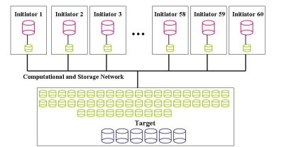
Also, let's assume that each initiator node gets 50 GB of storage. This configuration means that the target node will export 60 block devices that are 50 GB partitions of the six drives. In Figure Fourteen these are shown in green in the target node. Let's also assume that the block devices are exposed over a TCP network (at least GigE) that is shared with the computational traffic. This means that we can have up to 60 initiator nodes where each initiator uses one block device from the target node. Then the initiator nodes format a file system on its particular block device. In Figure Fourteen the block devices for the initiator are shown in green and the resulting local storage with a file system is show in red. This configuration is a basic configuration in that there is really no resiliency included in the design. However, it does give you the most usage of the disks in the target node.
We can modify the basic configuration of Figure Fourteen to add some performance or some resiliency. Figure Fifteen is the same basic configuration as Figure Fourteen but the drive configuration on the target node is different. In this case we can take a pair of disks and combine them using software RAID. For performance we would combine them with RAID-0 (simple striping) and for resiliency we could combine them with software RAID-1. Figure Fifteen illustrates the drives being combined with RAID-0.
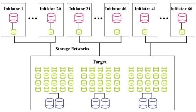
We use RAID-0 (stripping) on pairs of disks, resulting in 1TB of usable space on the pair. Using RAID-0 also gives us some extra performance. Then you break each pair into 20 block devices that each have 50 GB of space. This can be done using lvm. With six drives, this also gives you 60 block devices, one for each initiator.
This approach gives you the same number of block devices as the basic approach but you have some extra speed in this case because the underlying disks are using RAID-0. But it also means that the target node has to manage 20 md devices. However, in the interest of performance we have sacrificed resiliency.
Let's look at one last example in Figure Sixteen that adds some resiliency and performance to a basic configuration. Let's assume we have two iSCSI targets called Target 1 and Target 2 that only provide iSCSI storage space and are not used as a compute node. Each target node has five 500 GB drives configured in RAID-5 that are shown in blue in Figure Sixteen. It would probably be best to use hardware RAID for this configuration but you could use software RAID. For each Target, it works out to roughly about 2 TB of storage space (total of 4 TBs).
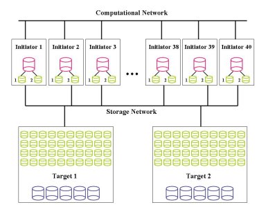
Each target node uses lvm to break the 2 TB storage space into 40 block devices of 50 GB each. In Figure Sixteen the block devices are shown in green. Remember that with iSCSI you don't put a file system on these block devices. These block devices are exposed to the initiators over a dedicated storage network as shown in Figure Sixteen. From each target machine there are 40 block devices that are from a RAID-5 group
Each initiator (client) uses a block device from Target 1 and a block device from Target 2. Then we can use software RAID (md) to combine the two block devices using RAID-1, resulting in the device, /dev/md0. Then /dev/md0 can be formatted with a file system. This is shown in red in Figure Sixteen.
There are several points of resiliency in this configuration. First, the target nodes are using RAID-5 which allows them to lose one disk without any lose of data. If it is well thought out, it could even use hot-swap drives. Second, there is a separate network for iSCSI. While not likely, if the computational network goes down the storage network could still be functioning (although this might be pointless). The storage network also allows increased speed because you are not combining storage and computational traffic on a single network. Third, the initiator nodes are using RAID-1 for their block devices. This means that if a block device fails for some reason, there is no lose of data. Fourth, the initiator nodes are using the two block devices from separate nodes. Therefore, an entire target node could go down without lose of data in the initiators.
So you can see that iSCSI gives you a lot of flexibility in configurations. You may pay a performance penalty because of the network, but if you need flexibility, iSCSI offers it. I have even designed some RAID-5 configurations so that each initiator mounts a block device from at least 5 different machines that are used in a md RAID-5 block device. This gives RAID-5 on the target machine and on the initiator. Since md supports RAID-6, it is also possible to form RAID-6 block devices in initiators.
There are lots of other options. You can take two target machines and use HA (High Availability) between them to tolerate a loss of a node without losing any data or up-time. You can also use multiple GigE networks (GigE cards are cheap) and run different block devices across each one. This adds resiliency and performance. Adding in resiliency and performance can raise the cost of the storage system but you are adding performance and resiliency.
Hopefully from these few examples, you can see that there are lots of options for creating iSCSI storage systems. You can actually spend an afternoon designing iSCSI systems, determining prices, resiliency, and performance and still not scratch the surface of the options. So you can see that using iSCSI offers a tremendous amount of flexibility for providing cluster storage.
AoE
A close cousin to iSCSI and HyperSCSI is AOE (ATA over Ethernet). It was developed by CoRaid for creating and deploying inexpensive SAN systems using ATA or SATA drives and Ethernet. Like HyperSCSI, AoE uses its own packet that sits on top of the Ethernet layer. And like iSCSI and HyperSCSI it encapsulates hard drive commands and transmits them over an Ethernet network. But the specification for AoE is only 8 pages long and the specification for iSCSI is 257 pages. The difference is because AoE uses ATA commands and not SCSI commands.
AoE was developed quite quickly using a simple design. An AoE driver was added to the Linux kernel very rapidly. In this drive for simplicity, it was decided to use a different packet design than TCP. This improves performance, but it makes the packets unroutable over WANs. But since most SANs don't use WANs, then this isn't too much of a problem. More over clusters don't use SANs so this is not an issue.
AoE is very unique in that it uses a MAC Address to identify both the source and destination of the packets. Remember that AoE uses packets defined just above the Ethernet layer. So this means that the MAC address approach can only work inside a single Ethernet broadcast domain. It also means that the checks of TCP can't be used. So AoE has had to develop its own flow control techniques. It uses cyclic redundancy checks to ensure that the packets arrive intact.
CoRaid has written drivers for AoE for a variety of platforms. They have drivers for Linux (part of the 2.6 Linux kernel), FreeBSD, Mac OS X, Solaris, and God help us all, Windows. So it's pretty easy to use AoE with a variety of operating systems.
CoRaid has developed a set of products that use AoE to provide block devices to nodes in a very similar manner to iSCSI. They have a 3U rack enclosure that has up to 15 slots for SATA I or SATA II drives. It also has 2 GigE connections to connect the storage to the cluster network. It has a RAID controller inside the unit for the drives and has redundant hot-swap power supplies. With the two GigE links, the aggregate performance of a single box is about 200 MB/s.They also have other form factors including a 1U with 4 drives and a tower with 15 drive slots. There is a fairly new box that has a 10GigE link in or 6 GigE links with performance of about 500 MB/s. They also have a 4U device that has 15 drive slots, but also has a small NAS/CIFS server built in to make a simple NAS/CIFS box.


